
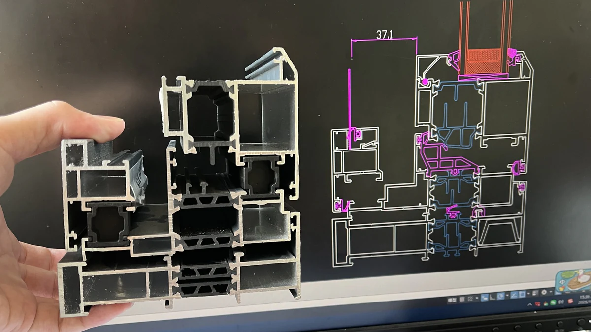
1. Balance adjacent wall thicknesses
A heavy flange beside a very thin web makes metal flow and cooling more difficult to balance. The example of a 4.0 mm flange beside a 0.8 mm web illustrates the issue. Gradual transitions, revised ribs or local hollowing may improve the section without sacrificing its required strength.
A thickness ratio such as 2.5:1 can be used as an early screening guide for adjacent features, but it is not an approval limit for every die. Alloy, circumscribing circle, section symmetry and the function of the thick area all need review. Keep necessary load paths and fastening support in the design.
2. Choose practical walls for the alloy and section
Planning examples include walls around 1.0–1.2 mm for some 6063 designs and around 1.5–2.0 mm for some 6061 designs. These are discussion ranges, not universal minimum wall capabilities. A large section, deep cavity or difficult tongue can need more material than a small, simple shape.
Compare the total part cost rather than weight alone. A thinner wall that slows extrusion, increases rejects or complicates handling may cost more overall. The approved die drawing should state the walls and tolerances that matter to the finished assembly.
3. Review deep, narrow slots early
Deep slots leave slender features in the die that can be difficult to support and cool. As a preliminary design check, compare slot depth with opening width. A simple depth-to-width ratio around 3:1 may already merit review; much deeper features, including some heat-sink designs approaching 8:1, require specialist assessment.
This simple slot check is not the complete tooling calculation for an industry tongue ratio. Die designers also consider the area and support of the die tongue, alloy, flow and press conditions. Opening a slot, shortening a fin or changing the local shape may make a marginal section more practical.
4. Use radii where the function allows
Small radii around R0.5–R1.0 mm can reduce sharp transitions and help metal flow, handling and coating coverage on suitable designs. Identify corners that must remain sharper for a mating part, seal or visual requirement. A standard radius should not silently replace a critical corner on the customer's drawing.
5. Compare open and closed section options
A fully enclosed cavity generally needs a different die arrangement from a simple solid or open shape. If the function permits it, opening a non-critical cavity can simplify the tooling and reduce unnecessary metal. A semi-hollow design is not automatically cheaper, however: a weak, narrow opening can make the die more demanding. Review both options with the tooling team.
6. Mark visible A-surfaces
Identify the faces that customers will see after installation, including surfaces that become visible only when a door opens. The die layout, flow and porthole weld-line positions should be reviewed with those faces in mind. Powder coating or anodizing does not automatically hide every extrusion mark, so appearance criteria belong in the sample approval.
7. Design helpful fabrication features
An agreed locating groove, for example a small 0.5 mm V-feature where appropriate, can help position later drilling. Screw ports, reference faces and accessible clamping areas may also reduce machining effort. They do not eliminate the need for suitable fixtures or inspection. Check that any locating feature does not weaken the section or interfere with a visible face.
8. Consider straightness and twist as assembly requirements
An unbalanced section may be more sensitive to differential cooling, bow and twist. Review the cross-section alongside the final bar length, quenching route, stretching and downstream supports. State the required straightness over a defined measurement length, together with the twist criterion and inspection method. A long industrial rail needs a different functional review from a short decorative trim.
Examples of useful design changes
| Design issue | Possible revision | What to validate |
|---|---|---|
| An oversized solid boss adds weight. | Hollow or lighten material away from the load path. | Fastener support, strength and the achievable section weight. |
| A 2 mm opening extends 12 mm into the section. | Open or shorten the slot, or redesign the mating interface. | Die support, component retention and finished clearance. |
| Sharp transitions sit on a coated face. | Add suitable radii where permitted. | Appearance, coverage and compatibility with mating parts. |
| A long section has uneven material distribution. | Rebalance ribs or wall transitions. | Stiffness, extrusion stability, bow and twist after processing. |
In a Guantian engineering example, a section with a 6.5 mm base and 1.8 mm flange was reviewed using local lightening grooves and R0.8 transitions. The revised meter weight changed from 3.40 to 2.85 kg/m, a reduction of approximately 16.2%, while the revised process improved flatness for that project. This is a specific design result, not a promised saving for every extrusion.
Frequently asked questions
Can you review a drawing before we pay for a die?
Yes. Send the section, intended application, quantity, alloy, finish and critical requirements for an initial DFM discussion. The agreed drawing revision and quotation define the manufacturing scope before tooling starts.
What section size can your current presses handle?
The 800T–1500T lines can review suitable sections around a 200–220 mm circumscribing circle, depending on alloy, geometry and production requirements. A circle dimension alone does not establish feasibility. The planned Sihui base is expected to enter operation in 2027 and is not part of today's installed capacity.
Can a 3D-printed concept be redesigned as an extrusion?
Often, a constant cross-section can be extruded and local holes or pockets added through secondary fabrication. Features that change continuously along the length may require another process. Send the model and identify the surfaces and functions that must be retained.
Arrange a DFM review
Send the DWG or PDF section, a STEP model if available, the assembly requirements and estimated annual volume. Mark critical dimensions and visible faces. Contact us on WhatsApp; our sales team normally responds within 24 hours and agrees the engineering review schedule for the project.