
Why a general profile specification may not be enough
A long rail can meet a general dimensional standard yet still bind a particular slider or roller cartridge. A small change at the slot mouth can remove the intended running clearance. A 0.25 mm opening change illustrates why the buyer should identify the functional interface rather than leave every dimension under one general tolerance.
Load performance also depends on the section geometry and support spacing. Hardness or a T6 temper alone does not establish the safe working load. Repeated contact from steel rollers, concentrated loads, impact and fastening torque should be considered by the system designer. Do not select 6061 or 6063 from a single headline strength figure without reviewing the application.
Long hole patterns introduce another issue: the stock must be supported and located consistently during cutting, punching or drilling. Bow, datum selection and temperature changes can affect how the final mounting holes align with a steel sub-frame. Specify the cumulative pattern requirement as well as the distance between adjacent holes.
Controls to include in the drawing and inspection plan
| Critical requirement | What can go wrong | Manufacturing and inspection approach |
|---|---|---|
| Alloy and temper | The rail or thread does not meet the intended mechanical requirement. | Confirm the alloy, temper, product standard and acceptance tests; use hardness as an agreed process check. |
| Track opening and lip angle | The slot closes or flares and the slider jams or becomes loose. | Review die compensation, inspect the critical opening and trial the actual mating component or a dedicated gauge. |
| Straightness and twist | A long rail rubs or guides the moving component unevenly. | Coordinate quenching, controlled stretching and support; inspect over the agreed length and datum. |
| Hole pattern and edge condition | Mounting holes drift or burrs interfere with moving parts. | Use suitable stop gauges, fixtures or partner CNC operations; agree deburring and swarf-removal checks. |
| Sliding surface and finish | Wear, friction or surface damage disrupts movement. | Select an appropriate finish and validate the finished running clearance with a sample assembly. |
Guantian's process examples include 6061-T6 guide rails checked around 15–17 HW on a Webster tester and 6063-T5/T6 sections with application-specific hardness criteria. These are project examples, not substitutes for the required mechanical properties in the applicable material standard. Test method, wall thickness, location and calibration affect hardness readings.
Controlled stretching can help manage bow and twist after extrusion. A process range of approximately 1.5–2.5% is subject to the alloy, section and production route; it is not an instruction to stretch every profile by the same amount. The acceptance requirement should describe the finished straightness and twist, not only a machine setting.
A flow-rack guide-rail project
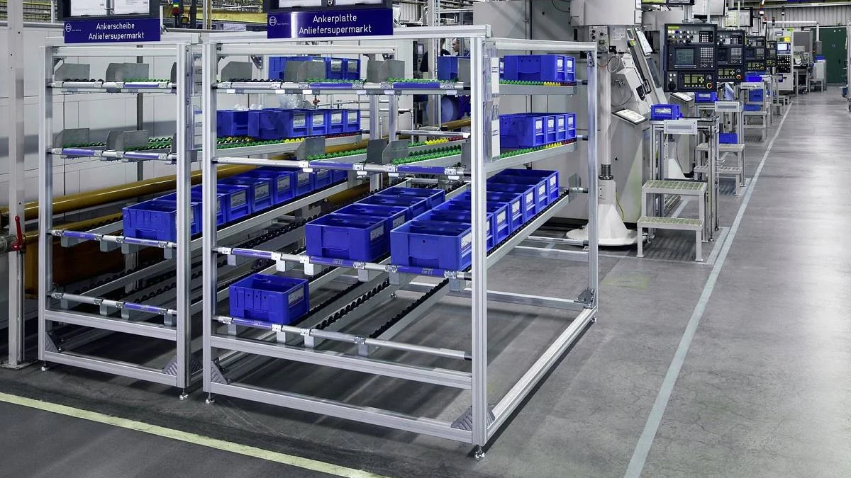
In the Guantian project described here, an industrial storage-equipment customer needed to address roller binding and rail deformation. The manufacturing review combined the alloy, die interfaces, hole pattern and finished assembly rather than treating these as unrelated defects.
- Material: the load-bearing guide rails used 6061-T6, with the agreed aging and batch-hardness checks, including reported results around 15–17 HW.
- Fit: the customer's actual plastic roller cartridges and end connectors were used to review the guiding ribs. A project-specific critical dimension was controlled to ±0.12 mm.
- Fabrication: the rails were cut and their mounting slots punched in-house, with suitable cleaning before partner anodizing.
- Verification: dimensions and straightness were checked on suitable inspection supports, followed by a practical fitting trial with the mating components.
The customer achieved drop-in assembly without field rework for that supplied project. That result supports the value of coordinated review; it does not establish a universal zero-rework guarantee for different rail designs. See the linked flow-rack case study for the project context and discuss an equivalent trial for your own assembly.
Choose the finish around the sliding interface
Clear or black anodizing can be considered for industrial rails because it forms an integral oxide layer with useful wear characteristics. Example projects may specify around 10–15 micrometers, while other applications need a different system. Anodizing still changes dimensions and is not dimensionally zero; account for its growth and any sealing or post-treatment in the fit review.
A powder film around 60–80 micrometers can consume more clearance and may be unsuitable at a continuously rubbing interface unless the system is designed for it. Surface roughness, lubrication, the mating material and actual contact load also affect wear and friction. Approve the finished rail with the actual roller or slider rather than choosing by appearance alone.
Frequently asked questions
Can you supply T-slot profiles for standard fasteners?
Existing dies or custom sections can be reviewed for 20, 30, 40, 45 and 80 series systems. Confirm the exact slot, nut and bracket dimensions with samples. A series name or resemblance to a Bosch- or item-style system does not establish universal compatibility or brand affiliation.
Can we order brackets, T-nuts and end caps with the profiles?
Yes. Matching fasteners, suitable corner brackets and plastic end caps can be coordinated for an agreed bill of materials and consolidated shipment. Approve the component specification and assembly before bulk procurement.
Which information is needed for a rail trial?
Provide the section and machining drawings, load and support arrangement, required material properties, straightness and twist limits, finish, order length and actual roller or slider details. Highlight the dimensions that control movement and attachment.
Discuss your industrial profile project
Contact us on WhatsApp with the drawings and mating-part information. Our sales team normally responds within 24 hours and arranges the engineering review, sample plan and tooling or per-piece quotation according to the project requirements.