
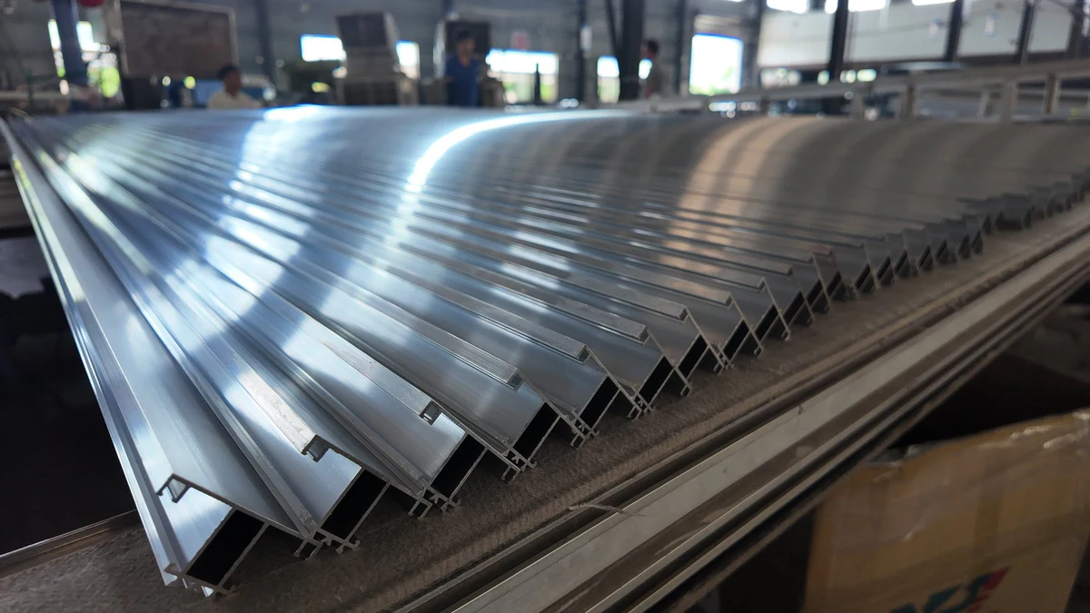
Separate critical dimensions from general dimensions
A profile drawing may contain many dimensions, but only some determine the fit of a gasket, fastener, bearing or adjoining profile. Identify those dimensions explicitly. Applying an unnecessarily tight tolerance to every feature can increase tooling work, inspection effort and rejection without improving the finished assembly.
Use a consistent datum system for hole locations and machined features. State how an open channel should be measured and whether the profile may be restrained during inspection. Thin walls and unsupported arms can move under measurement pressure, so the inspection method should reflect the condition in which the component is used.
State the condition in which dimensions apply
Write "dimensions apply after powder coating" or "dimensions apply before anodizing" where appropriate. Without this distinction, the extrusion may pass an unfinished inspection yet fail to accept a mating component after finishing. Also identify masked areas, areas requiring electrical contact and surfaces that will be machined later.
As an illustrative calculation, a 70-micrometer powder coating on each of two opposing slot walls would reduce the opening by approximately 0.14 mm if both walls receive that thickness. Actual buildup varies with geometry and coating distribution. This calculation explains why clearance needs review; it does not replace a finished sample or establish a standard die correction.
Treat each finishing process separately
Powder coating adds a layer to the surface. Recessed channels, corners and exposed edges may not receive the same buildup, so a nominal film thickness alone cannot predict every finished dimension. Wood-grain transfer also requires the underlying coating system to be considered when reviewing assembly clearance.
Anodizing forms an oxide layer partly within the original surface and partly above it. Net dimensional change also depends on pretreatment and the process used. It is therefore inaccurate to treat the full anodic film thickness as outward growth on every surface, or to assume that a thin anodized layer never affects precision fits. Review close-fitting features with the finishing partner.
Resolve geometry and machining requirements together
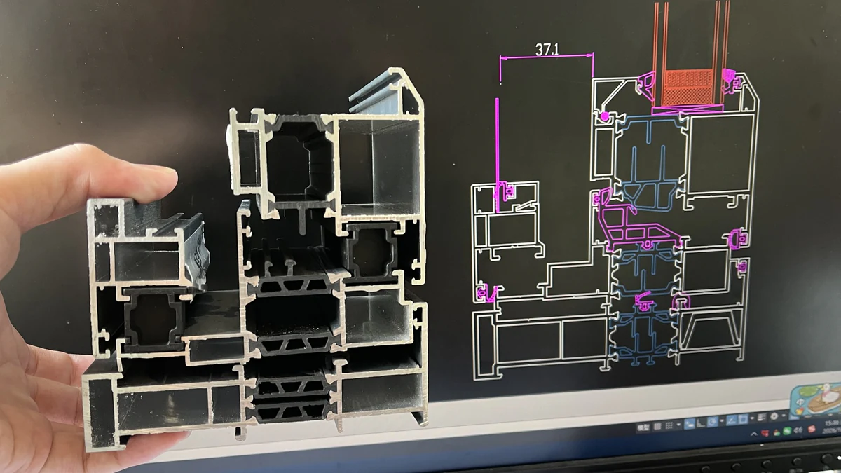
Deep slots, long unsupported arms and uneven wall thickness can make a section more sensitive to deformation during extrusion and subsequent handling. Engineering changes may include local radii, more balanced walls or another section arrangement. The choice must preserve the customer's functional requirements rather than simply make the die easier to produce.
Some features are more practical to finish by machining after extrusion. Guantian performs cut-to-length sawing and standard punching in-house, while specialist partners handle drilling, tapping and more complex CNC operations. Machining allowance and final tolerances are reviewed for the actual feature, component length, fixturing and equipment. Do not apply a blanket machining allowance to every surface.
| Drawing item | Information to include |
|---|---|
| Mating channel or cavity | Component dimensions, required clearance and finished condition |
| Visible surface | Appearance reference and any restrictions on marks or contact points |
| Machined hole or face | Datum, position or flatness requirement and inspection method |
| Long profile geometry | Reference length and limits for straightness or twist |
| Mating profile pair | Both drawings and an agreed functional fit check |
Use sample evidence to confirm the allowance
Guantian's documented window project used an additional 0.15 mm on each side of selected hardware and gasket channels to accommodate the specified powder coating. Engineers reviewed the actual components before tooling. The amount was specific to that cross-section, finish and assembly; applying it unchanged to another profile could create excessive clearance.
For a new project, compare the approved drawing with measurements from the unfinished and finished samples. Record the mating-component reference and confirm the functional test. If two profiles interlock, assess them together under the agreed assembly conditions. A retained sample helps communicate acceptable fit during later production, but the drawing and measurable acceptance criteria should remain clear.
Frequently asked questions
What is your standard extrusion tolerance?
We review general and critical tolerances against the section, alloy and applicable drawing requirements. Send the drawing so that the relevant production and inspection limits can be confirmed.
Can every tight feature be achieved directly by extrusion?
No. Some dimensions or surfaces require machining after extrusion. The engineering review identifies a practical route before the quotation is finalized.
Why can fit vary between the ends of a long profile?
Section variation, local distortion, straightness, die condition and finishing can influence fit. The inspection plan should cover relevant positions along the length rather than only one cut section.
Should we send our mating components?
Yes, where practical. Drawings remain important, but actual components can clarify gasket retention, sliding movement and other assembly requirements during sample evaluation.
Request a drawing and fit review
Send the extrusion drawing, mating-part details, finish and required delivery condition to [email protected]. Mark the dimensions that directly affect assembly so that we can review tooling, finishing and any partner machining together.